

High Precision Measurements
High Precision Measurements is a Ukrainian developer, producer and supplier of the specialized strain gages and accessories intended for tensile strength measurements at elevated and high temperature conditions since 2012. Our company produces wire strain gages for -269…+1150°C operating temperature range. Engineering team of our company comprises specialists in metrology, strength of materials and mechanical values measuring units. The core of our engineering team are specialists having years of practical experience of measurements and field tests at Motor-Sich factory. This particular experience helps us understand the acute needs of our customers. The motto of our company is our employees’ sincere interest in scientific research and engineering, desire for constant perfection of our products.
High Precision Measurements for many years has been an official representative of ZEMIC company for strain gages and accessories for measurements at elevated temperatures. Over these years we developed many special solutions for our customers, which allow to increase speed and comfort of the strain gage application and also increase precision of measurements.

When the beam is loaded, the upper strain gage is stretched (and its resistance increases), and the lower one is compressed (and its resistance decreases). When these strain gages are connected to the different arms of the bridge, the output signal of the bridge doubles (compared to the signal when only one working strain gages are connected to the bridge). And at heating of strain gages their resistance changes equally and at inclusion of these strain gages to the bridge their "synchronous" change of resistance does not cause the appearance of a signal at the bridge output. However, in reality there is inevitable non-ideality in the coincidence of temperature conditions for each of the SGs, as well as in the coincidence of the temperature change in their resistance, and even though small, but the signal at the output of the bridge will appear.
It should be noted that at very high temperatures (from several hundred to a thousand degrees and more), the temperature "response" of strain gages is many times greater than their "response" to strain. This is not a problem when measuring dynamic strain, when the slow change of the signal due to the influence of temperature is simply "filtered out" by strain gage equipment, but measuring static strain at high temperature is a difficult technical task. A typical technique for static strain gauging at high temperature is (in addition to the mandatory use of circuit compensation) the so-called temperature calibration of the part: the part with strain gages is heated to maximum operating temperature without mechanical loading and the dependence of strain gage readings on the temperature of the part is recorded. Then, during testing, a corresponding correction is made to the measurement results.
Why HPM?
HPM not only production company we are more focused on real tests, engineering and research work related to high temperature strain gauging.
Engineers prefer to work with us because of deep understanding of end users field of usage and problematics they face with. Core our team are engineers from test laboratories of Ukrainian jet engine production factory and Kyiv Polytechnic Institute so we deeply versed in strain gauging in theoretical and practical fields and able to help our partners to solve all kind problems at daily work.
At HPM, we take quality control seriously. Choose HPM with confidence, knowing that you are getting the best quality and service in the industry. We are proud to be certified to ISO9001:2015, which demonstrates our commitment to excellence. We understand that your time is valuable, that’s why we always provide a prompt feedback and shorter lead time than our competitors. In addition, our extensive range of products provides you with a wide variety of options to choose from.
To summarize the reasons why engineers prefer to work with our company
- Deep understanding of customer requests and problems.
- Output control which guarantees high quality products.
- Short lead times for feedback, production and delivery.
- Lowest prices for strain gage niche products and equipment.
- The ability to produce special cusomized products and equipments.
General information
Bondable high temperature gages are intended for measurements of deformations in the details of machinery and equipment, including jet engines and gas turbines, under static and dynamic loads in -269…+1150°C temperature range.
Strain gage can be produced of NiCr, FrCrAl or PtW alloys and fixed with the temporary carrier, of fiberglass-reinforced PTFE.

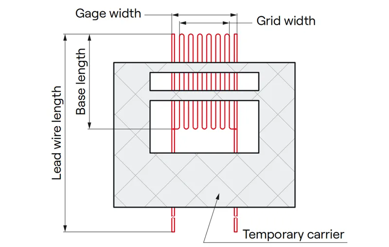
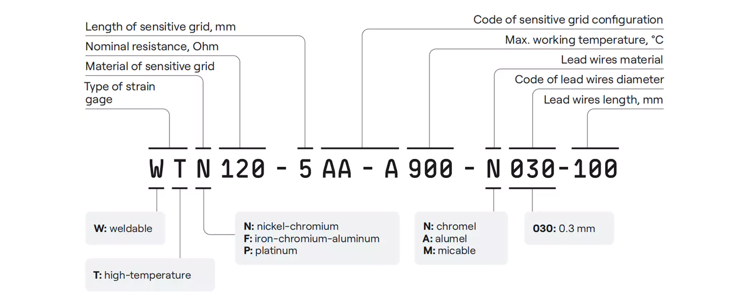
Schematic drawing Designation system

Packaging
Individual strain gages are supplied on plastic or glass carriers, can be covered with protective plastic foil. Each strain gage is labelled with the actual electric resistance values.
Groups of strain gages are packed in plastic boxes in amount of 1...25 pieces. Each group packing has a label with the main parameters of the gages, including resistance range of the gages group, gage factor, production date, etc.
Batches of strain gages are packed in plastic containers with or without auxiliary installation tools. Each batch container has a label with all main parameters of the gages, general description, batch number and production date.

STN series high-temperature strain gages
STN strain gages are the most common type of bondable high-temperature wire strain gages for static and dynamic loads in the temperature range up to +900°C. Sensitive grid of the gage is made of 15…30 um diameter nickel-chromium alloy wire. Sensitive grid is fixed on the fiberglass-reinforced PTFE temporary backing. Lead wires are made of ribbon or round wire with 0.07…0.15 mm diameter. Material of the lead wires correlates with the sensitive grid material and also nickel-chromium based.
Specifications
| Nominal parameters | Value | ||||
| Sensitive grid material | Nickel-chromium | ||||
| Possible number of sensitive elements | 1, 2 or 3 | ||||
| Base length, mm | 1.7-5.5 | ||||
| Gage width, mm | 1.6-2.6 | ||||
| Resistance, Ohm | 120-350 | ||||
| Resistance deviation in batch, not more than | ±1% or ±3% | ||||
| Lead wire material | Nickel-chromium | ||||
| Lead wire diameter, mm | 0.07-0.15 | ||||
| Lead wire type | Ribbon or round | ||||
| Lead wire length, mm | 50-300 | ||||
| Temporary carrier | Fiberglass-reinforced PTFE | ||||
| Average gage factor at 20°C | 2.05 | ||||
| Fatigue life at ±650 ppm at 20°C, cycles | 106 | ||||
| Bonding Methods | Ceramic Cement or Alumina flame spray | ||||
| Max. working temperature | 900℃ | ||||
| Type of measurements | Static and dynamic | ||||
Standard configurations
| Strain gage configuration | Designation | Nominal resistance, Ohm | Nominal base length, mm | Nominal grid width, mm | Lead wires length, mm |
 | STN120-1.7AA-A900-N010-50 | 120 | 1.7 | 2.2 | 50…300* |
| STN120-3AA-A900-N010-50 | 120 | 3.1 | 1.6 | ||
| STN350-3.5AA-A900-N010-50 | 350 | 3.4 | 2.6 | ||
| STN120-5AA-A900-N010-50 | 120 | 5 | 2.1 | ||
| *Other lead wire length can be supplied on request | |||||

STP series high-temperature strain gages
STP wire strain gages are platinum-tungsten based. They demonstrate perfect performance under dynamic loads in the temperture range up to +1150°C. Sensitive grid of these gage is made of 14…30 um diameter platinum-tungsten alloy wire. Sensitive grid is fixed on the fiberglassreinforced PTFE temporary backing. Lead wires are made of ribbon or round wire with 0.07…0.15 mm diameter. Material of the lead wires correlates with the sensitive grid material and is also platinum alloy based.
Specifications
| Nominal parameters | Value |
| Sensitive grid material | Platinum-tungsten |
| Possible number of sensitive elements | 1 |
| Base length, mm | 1.6-5.5 |
| Gage width, mm | 1.6-3.2 |
| Resistance, Ohm | 120 |
| Resistance deviation in batch, not more than | ±1% or ±3% |
| Lead wire material | platinum-based alloy |
| Lead wire diameter, mm | 0.07-0.15 |
| Lead wire type | Ribbon or round |
| Lead wire length, mm | 50-300 |
| Temporary carrier | Fiberglass-reinforced PTFE |
| Average gage factor at 20°C | 3.5 |
| Fatigue life at ±650 ppm at 20°C, cycles | 106 |
| Bonding Methods | Ceramic Cement or Alumina flame spray |
| Max. working temperature | 1150 ℃ |
| Type of measurements | Dynamic |
Standard configurations
| Strain gage configuration | Designation | Nominal resistance, Ohm | Nominal base length, mm | Nominal grid width, mm | Lead wires length, mm |
 | STP120-1.6AA-A1150-P007-45 | 120 | 1.6 | 3.2 | 50…300* |
| STP120-3AA-A1150-P007-45 | 120 | 2.95 | 1.6 | ||
| STP120-5AA-A1150-P007-45 | 120 | 5.5 | 2 | ||
| *Other lead wire length can be supplied on request | |||||
STF series high-temperature strain gages
Fe-Cr-Al alloy gages are designed for the use in the widest operating temperature range. These bondable high-temperature wire strain gages are dedicated for measurements of deformations in the details of machinery and equipment, including jet engines, under static and dynamic loads up to +1150°C temperature range. Sensitive grid of the gage is made of 15…30 um diameter iron-chromium-aluminum alloy wire. Sensitive grid is fixed on the fiberglass-reinforced PTFE temporary backing. Lead wires are made of ribbon or round wire with 0.07…0.15 mm diameter. Material of the lead wires correlates with the sensitive grid material and is also iron-chromium-aluminum based.
Specifications
| Nominal parameters | Value |
| Sensitive grid material | Iron-chromium-aluminum |
| Possible number of sensitive elements | 1 |
| Base length, mm | 1.9-3.5 |
| Gage width, mm | 1.6-2.7 |
| Resistance, Ohm | 120-350 |
| Resistance deviation in batch, not more than | ±1% or ±3% |
| Lead wire material | Iron-chromium-aluminum |
| Lead wire diameter, mm | 0.07-0.15 |
| Lead wire type | Ribbon or round |
| Lead wire length, mm | 50-300 |
| Temporary carrier | Fiberglass-reinforced PTFE or filter paper |
| Average gage factor at 20°C | 2.3 |
| Fatigue life at ±650 ppm at 20°C, cycles | 106 |
| Bonding Methods | Ceramic Cement or Alumina flame spray |
| Max. working temperature | 1150℃ |
| Type of measurements | Static and dynamic |
Standard configurations
| Strain gage configuration | Designation | Nominal resistance, Ohm | Nominal base length, mm | Nominal grid width, mm | Lead wires length, mm |
 | STF120-1.9AA-A1150-F015-50 | 120 | 1.9 | 2.3 | 50…300* |
| STF120-2.3AA-A1150-F015-50 | 120 | 2.3 | 1.6 | ||
| STF120-3AA-A1150-F015-50 | 120 | 3 | 1.3 | ||
| STF350-3.5AA-A1150-F015-50 | 350 | 3.5 | 2.7 | ||
| *Other lead wire length can be supplied on request | |||||

Wire rosettes
Wire strain gages rosettes can be made with two (BA configuration) or three (CA configuration) sensitive grids.
BA rosettes consist of two independent sensitive grids, oriented in different ways such as: V-type (0°-60° or 0°-45°) and L-type (0°-90°).
CA type rosettes consist of three independent sensitive grids, oriented at 0°-45°-90° or 0°-60°-120° and are intended for determination of complexly oriented deformations.
EA type rosettes consist of five independent sensitive grids, well known also as chains of strain gages and are intended for determining the most deformed point.
Gages are to be installed on the surface of the test object using ceramic cement adhesive or alumina flame spray method.
Gages are provided on the temporary fiberglass-reinforced PTFE carrier, which is subject to removal during installation of the strain gage.
Specifications
| Nominal parameters | Value |
| Sensitive grid material | FeCrAl, NiCr or PtW |
| Possible number of sensitive elements | 2 or 3 |
| Nominal strain gage base length, mm | 3-3.5 |
| Resistance, Ohm | 120-350 |
| Resistance deviation in batch, not more than | ±3% |
| Lead wire material | FeCrAl, NiCr or platinum-based alloy |
| Lead wire diameter, mm | 0.07-0.15 |
| Lead wire type | Ribbon or round |
| Lead wire length, mm | 50-300 |
| Temporary carrier | Fiberglass-reinforced PTFE |
| Types of BA configuration wire rosettes | T-type, L-type and V-type |
| Types of CA configuration wire rosettes | 0°-45°-90° or 0°-60°-120° |
| Types of EA configuration wire rosettes | Chains of strain gages |
| Fatigue life at ±650 ppm at 20°C, cycles | 106 |
| Bonding Methods | Ceramic Cement or Alumina flame spray |
| Type of measurements | Static and dynamic |
Standard configurations
| Strain gage configuration | Designation | Nominal resistance, Ohm | Nominal base length, mm | Nominal grid width, mm | Lead wires length, mm |
 | STN350-3.5CA-A900-N015-50 | 350 | 3.4 | 2.6 | 50~300 |
| STF350-3.5CA-A1150-F015-50 | 350 | 3.5 | 2.7 | ||
| STP120-3CA-A1150-P007-45 | 120 | 2.95 | 1.6 | ||
 | STN350-3.5CA-B900-N015-50 | 350 | 3.4 | 2.6 | |
| STF350-3.5CA-B1150-F015-50 | 350 | 3.5 | 2.7 | ||
| STP120-3CA-B1150-P007-45 | 120 | 2.95 | 1.6 | ||
 | STN350-3.5CB-A900-N015-50 | 350 | 3.4 | 2.6 | |
| STF350-3.5CB-A1150-F015-50 | 350 | 3.5 | 2.7 | ||
| STP120-3CB-A1150-P007-45 | 120 | 2.95 | 1.6 | ||
 | STN350-3.5EA-A900-N015-50 | 350 | 3.4 | 2.6 | |
| STF350-3.5EA-A1150-F015-50 | 350 | 3.5 | 2.7 | ||
| STP120-3EA-A1150-P007-45 | 120 | 2.95 | 1.6 | ||
 | STN350-3.5BB-A900-N015-50 | 350 | 3.4 | 2.6 | |
| STF350-3.5 BB-A1150-F015-50 | 350 | 3.5 | 2.7 | ||
| STP120-3 BB-A1150-P007-45 | 120 | 2.95 | 1.6 | ||
 | STN350-3.5BC-A900-N015-50 | 350 | 3.4 | 2.6 | |
| STF350-3.5 BC-A1150-F015-50 | 350 | 3.5 | 2.7 | ||
| STP120-3 BC-A1150-P007-45 | 120 | 2.95 | 1.6 | ||
| Note: According to customer requirements, can be designed special configuration and size. All high temperature wire strain gages can be customized. | |||||

TG series foil strain gages
TG series strain gages are produced from iron-chromium-aluminum (Fe-Cr-Al) alloy foil by wet etching process. They are intended for the measurements of static deformations and mechanical tensions in the 269…+800°C temperature range. Installation of the gages on the test object is done with a special high-temperature ceramic glue, e.g., CC-02.
While using TG series strain gages, temperature compensation is done by connecting the same strain gage in the adjacent branch of the measuring circuit. This allows to reach higher precision of the measurement.

Designation system

TG series strain gages are shipped on the temporary fiberglass-reinforced PTFE backing,which helps to keep the shape of the gage during the installation process. After installation the temporary backing is removed.
Each lead wire has electric resistance of10 Ohms. TG gage resistance should be measured at the center of the lead wires (25 mm from the loose end), then the measured resistance will be 350±0.3% Ohm.
Standard configurations
| Strain gage configuration | Designation | Nominal resistance, Ohm | Nominal base length, mm | Nominal grid width, mm | Lead wires length, mm |
 | TG350-5AA800-YF50 | 350±0.3% | 5 | 3.66 | 50~300* |
| TG350-3AA800-YF50 | 350±0.3% | 3 | 5.11 | ||
| TG120-5AA800-YF50 | 120±0.3% | 5 | 2.47 | ||
| TG120-3AA800-YF50 | 120±0.3% | 3 | 2 | ||
 | TG350-3BB800-YF50 | 350±0.3% | 3 | 7.72 | |
 | TG350-3HA800-YF50 | 350±0.3% | 3 | 5.53 | |
 | TG350-3FB800-YF50 | 350±0.3% | 3 | 8 | |
| Note: According to customer requirements, can be designed special configuration and size. All high temperature foil strain gages can be customized. | |||||
General information
The weldable strain gage is a special resistance strain gage that inherits the typical characteristics of a universal strain gage preinstalled on piece of foil, especially for metal structures, precision stress measurement and analysis.
HKB series weldable strain gages for midtemperature
HKB series strain gages are weldable strain gages with IP67 protection class. They are used in harsh conditions, when standard bonding of the gages is impossible due to high humidity, impossibility to clean the test object, etc. These strain gages are installed on the test object using dot spot welding machine. Operating temperatures range is -30…+250°C.
Designation system

Specifications
| Nominal parameters | Value |
| Sensitive grid material | Karma foil |
| Backing material | Glass fiber reinforced polyimide |
| Base body material | Stainless steel |
| Base body thickness (mm) | 0.1 |
| Typical resistance (Ohm) | 120 - 350 |
| Resistance tolerance | ≤±0.1% |
| Typical sensitivity coefficient | 1.70~2.1 |
| Sensitivity coefficient dispersion | ≤±2% |
| Use temperature range | -30ºC~250ºC |
| Strain limit | ±3000 μ ε |
| Protection mode | Silicone protection |
| Installation method | Spot welding installation |
Installation method
Spot welding (e.g. using CDWT-6001 spot welding machine). Rough polishing of the installation surface is recommended if possible.
Standard configurations
| Strain gage configuration | Designation | Nominal resistance, Ohm | Nominal base length, mm | Nominal grid width, mm | Lead wires length, mm |
 | HKB120-3AA (11)-G** | 120±0.1% | 6.4×3.5 | 14.6×8.9 | 50~300* |
| HKB350-3AA (11)-G** | 350±0.1% | 7.0×3.8 | 14.6×8.9 | ||
 | HKB120-3CA-T(11)-G** | 120±0.1% | 11.7×8.5 | 15.5×14.9 | |
 | HKB350-3BB-A(11)-G** | 350 ± 0.1 % | 8.5×6.5 | 13.7×13 |
Precautions
- Weldable strain gages should be stored in a dry, cool environment, to prevent the metal base body is oxidized.
- In the installation of the weldable strain gage, must fully polish and remove the oxide, glue film, stains of the welding area, otherwise resulting in low welding strength or poor welding and other quality issues.
- Before spot-welding the strain gage, please trial welding the test piece in order to find out the appropriate welding parameters to ensure the good quality for the official installation. (Welding trial piece is stainless steel piece with the same thickness as the weldable strain gage, 1 to 2 pieces will be supplied by the manufacturers freely.
- After a while of the usage of the Spot-welding machine, the welding hand electrode will be oxidized, need to be re-polished by using sandpaper or rasp. Otherwise if continue to use the machine, there will be sparking on the welding electrode and metal base body (with strong light and large sound).
- The installation of the weldable strain gage, please wear the protective glasses and protective gloves, so as not to harm the eyes and arms by the sparks.
- When use spot-welding machine to install the strain gage, must ensure the reliable grounding, the surrounding environment has no splashing liquid, to eliminate the possible shock risk factors.
If you have special requirements or other requirements, please contact and communicate with us in time. The sensitive coefficient of the weldable strain gage is about 10% smaller compared to the bondable strain gage.
WTN series weldable strain gages for high-temperature
WTN series weldable high temperature strain gages are intended for measurements of deformations in the details of machinery and equipment under dynamic loads in 269…+900°C temperature range.
These gages are intended for installation in places where bonding with ceramic cements is not possible either due to complication in surface preparation (polishing, degreasing, etc.) or due to large dimensions of the test object (cannot be thermally treated for cement curing).

Construction-wise a WTN series strain gage is a STN series wire strain gage, installed on a small piece of thin metal foil with ceramic cement.
Sensitive grid of the gage is made of 15…30 um diameter nickel-chromium wire.
Backing material is an oxidation and corrosive resistant nickel-chromium superalloy. This material is selected to match the thermal expansion coefficient of the sensitive grid.
Sensitive grid is installed on the backing using high temperature ceramic cement, applicable for long-term operation at 900°C. Ceramic cement also acts as an insulator layer between backing and the grid. Cement layer is protected against humidity with an organosilicon varnish.
Lead wires are made in a 2-core of nickel, alumel or micable in silica braid sheath. Typical diameter of the cores is 0.3 mm, but can be changed on demand. Typical length of the lead wires is 100 mm
Designation system

CC-02 High-temperature cement glue
General information: High-temperature cement is a green color pastelike inorganic ceramic adhesive, having good adhesion and excellent endurance after polymerization. Green pigment has been added to the composition which allows visual determination of the optimum thickness of the cement layer.. Max. operating temperature of this adhesive is 900°C (short term – up to 950°C).
Main Application: For high temperature strain gages bonding.

Surface preparation requirements:
To achieve superior bonding strength, a mechanical treatment of the installation is required. Sandblasting is the best way to prepare the surface, but sanding with sandpaper #80...120 grit also produces good results. Sanding may not be acceptable for turbine blades and other components working under high mechanical tension.
Polished area must be cleaned out with acetone several times to guarantee that the surface is absolutely clean and greaseless. After this, it is prohibited to touch the treated surface.
Storage conditions
At normal conditions in the original packing, shelf life of the cement glue is 6 months. After opening of the bottle, shelf life is 1 month.
Precautions and recommendations
- Please avoid direct contact of the cement glue with exposed skin, mucous membranes or respiratory system.
- After long-term storage of the cement glue, before usage and during usage it is needed to mix the bottle content thoroughly until the solution becomes homogenous.
- To prevent evaporation of the solvent, comprised in the cement glue, the bottle with the glue must be tightly closed during all time when it is not used.
- If the cement glue dried out during storage, it is possible to regulate its viscosity by adding deionized water. Please consider that doing so can influence the glue polymerization process.
Packing
1 bottle: 20g/bot.
Shelf life
6 months after production; 1 month after opening.

Surface preparation agents
Surface Conditioner SC Nº3 and Neutralizer NC Nº3 are special solutions designed for finishing surface cleaning from contaminants not removed by wiping the surface with alcohol or other solvents and for the formation of a film on the surface of the workpiece to ensure maximum adhesion of ceramic cement and organic glues.
Surface Conditioner SC №3
Main application
Solution for cleaning the surface of impurities not removed by wiping with alcohol or other solvents and preparing the surface for the application of ceramic cement.
Key features
Provides good wetting of the surface and forms a film on the surface of the workpiece, which increases the adhesion of ceramic cement.
Shelf life
12 months.
Method of application
Wipe the surface with a lint-free cloth or cotton bud moistened with the solution, if necessary, repeat several times until wetting of the surface with the solution is achieved. Then wipe off with a clean, dry, lint-free cloth.
Packing
20 or 30 ml glass bottle.
Neutralizer NC №3
Main application
Solution to neutralize residual of SC Nº3 conditioner before applying ceramic cement.
Key features
Neutralizes residual of SC Nº3 conditioner, provides final cleaning of the surface before ceramic cement application.
Shelf life
6 months.
Method of application
Wipe the surface with a lint-free cloth or cotton bud moistened with the solution, wipe with a dry cloth, air dry.
Packing
20 or 30 ml glass bottle.
Consumables and installation kits
For our customers, we also provide sets of tools and consumables that may be useful when working with strain gages.


Set of consumables may include
- Colored heat shrink tube for marking of the wires — used for marking of leads of strain gages. (Optional: 40 pcs. and 64 pcs. Diameter from 1 to 1.5 mm. Shrinkage when heated about 40%).
- Transparent heat shrink tube to protect markings from oil or kerosene (diameter 2-3 mm).
- Glass stocking (diameter of 1-5 mm).
- Flat synthetic brush No. 1, 2, 3.
- PTFE tape. Thickness 0.05 mm, width 30 mm (or a multiple of 60 or 90 mm). Tape length a multiple of 1 m.
- Polyimide tape (Kapton). Width 30mm, Roll length 33 m. Application temperature up to 300°C.
- Heat resistant tape (PET). Width 30mm, Roll length 33 m, Application temperature up to 200°C.
- Marker pen, thin (0.3 mm).
- Round synthetic brush No. 1, 2, 3.
Note: The installation kits may differ from those shown in the picture due to customers’ needs and requests.
Set of tools may include
- Cutters, precision side cutters.
- Pliers 2 pcs.
- Medical scissors ~150 mm, manicure scissors.
- Ruler.
- Tweezers: 1) straight thin, 2) curved thin, 3) wide.
- . Awl.
- Spatulas: 1) with straight ends 2) with a "spoon".
- Modelling knife (scalpel) with oblique blade Nº11 + spare blades (10 pcs).
- Surgical scalpel with interchangeable semicircular blades #23 + spare blades (10 pcs.)
- Needle file set.
- Magnifying glass.
- Flat and thin brushes 5 (10) pcs. each
- Metal spring clamps (for the possibility of maintenance in the furnace) ~100, 150 mm.
- Electronic scales 50g/0,001g.
- Mechanical pencil 0,5 mm + rods.
- Permanent marker 0.5 mm.

Thermocouple cable HRTW-CA
Cable decoding HRTW-CA
- H- Heat
- R- Resistant
- T- Thermocouple
- W- Wire
- CA- Chromel — alumel
- CC- Chromel-copel

General information
Thermoelectrode heat-resistant wire HRTW-CA designed for use as thermoelectrodes/extension wires for thermoelectric convertrs (thermocouples). It can be used in high temperature areas with fixed mounting and no mechanical load on the insulation.
The wire is designed for operation at ambient temperature from -60°C to +1200°C and maximum permissible humidity up to 80% at temperatures up to +35°C.
After heating to +450°C, it is not allowed to subject the wire insulation to mechanical stress and kinks. The wire is non-flammable.
The compensating wires are included in the thermocouple circuit in compliance with the polarity sign.
Cable design elements
Two-core thermocouple heat-resistant wires with conductive cores made of a pair of alloys: chromel-copel and chromelalumel, with varnish soaked organosilicon thread.
Purpose of HRTW-CA
They are used as thermocouples for fixed mounting in the absence of mechanical stress on the insulation during operation. Working temperature from –60°C to +900°C (or shortly up to 1200 °C).
CDWT-6001 capacitive discharge welding tool
Portable autonomous capacitive discharge welding tool is intended for the following tasks:
- Mounting of weldable strain gages with metal foil carrier up to 0.2 mm thick on metal details and assembly parts.
- Leading of elongation wires along details and assembly units, when such wires are fixed on the surface with 0.05 to 0.2 mm thick metal band stripes.
- Protection of the wires with full covers made of 0.05 to 0.2 mm thick metal foil, welded to the surface of details and assembly units.
- Welding of elongation wires to the lead wires of strain gages.
- Welding of thermocouples to details and assembly units; creation of inertia-free thermocouples.
- Other works requiring welding of thinsheet metal material (foil) up to 0.2 mm thick to details and assembly units.
- The tool can be used for welding of details from carbon steel, stainless steel, heatresistant steel, heat-resistant alloys; titanium, nickel, nickel-chromium, and nickelchromiumaluminum alloys.
Product specifications
- Built-in accumulator battery charging port: USB type C.
- Built-in accumulator battery charging current: 1 A.
- Control block dimensions: 156x180x52 mm
- Control block weight: 1.3 kg
- Length of ground clamp cable: 0.7 m
- Length of welding gun cable: 1 m.
- Battery charge is sufficient for at least 5000 welding points when working with 0.1 mm foil.

Capacitor battery recharge time after performing welding is:
At power levels 0 to 7 – not more than 1 s; At power levels 8 and 9 – not more than 1.5 s.
Set of supply
1 pc, cable with welding gun – 1 pc, charger – 1 pc, USB type C cable – 1 pc, product datasheet – 1 pc.
Tool for reproducing of deformations at high temperatures HTDR-1001
The HTDR-1001 device for reproducing of deformations at high temperatures (hereinafter - Device) is intended for determination of parameters of strain gages such as: gage factor, creep and mechanical hysteresis in the temperature range from 20 to 1000°C.
Structure and parameters of the Device
The principle of operation is based on the deformation of a beam of constant cross-section (calibration beam) by the scheme of pure bending. Depending on the deflection of the beam, the relative deformation of the lower and upper surfaces of the beam is being determined.
The Device consists of a loading device, graduation beam, beam heating system, strain calibration device and deflection meter. The loading device consists of a frame, a fixed traverse fastened to the frame, and a movable traverse. Each traverse is equipped with rollers, between which a calibration beam is installed.
As the movable traverse moves upwards, the upper fibers of the calibration beam are compressed, while the lower ones are stretched. Deformation of the beam is set using the deflection meter indicator installed on the beam surface.

TP-002T strain measuring device is used for multipoint measurements of static signals of strain gages (relative change in resistance of strain gages) and conversion of an analog signal into a digital one.
The calibration beam is made of a material that has a high limit of proportionality both at room and at elevated temperatures. When the beam is heated by electric current, its temperature is controlled by a thermoelectric transducer. Loading of the graduation beam is done manually by rotating the wheel on the front side of the device.
Signal from the strain gages installed on the graduation beam is collected in automatic mode using “Workstation for strain gages test” software, installed on a standalone PC. The software allows to input data and perform control from the keyboard, collecting signals by a predefined algorithm, mathematical processing of the data, display of obtained results and communication with other external devices.
Metrological parameters
| Parameter | Value | |
| Relative deformation measuring range, ppm | From -3000 to -100 | |
| and from +100 to +3000 | ||
| Limit of maximum deviation of relative deformation measurement, by subranges, ppm | -3000 to -500 and +500 to +3000 ppm | ±[8+0.004ε+0.05·Т]* |
| -499 to -100 and +100 to +499 ppm | ±[8+0.004ε+0.007·Т] | |
| Temporal instability of deformation maintenance, ppm | 50 to 80 |
* ε – result of measurement of the relative deformation, unsigned, ppm
T – deviation of the beam temperature from the normal temperature (20°C)
Technical parameters
| Parameter | Value | |
| Nominal dimensions of graduation beam, LxWxH, mm | 600x12x6 | |
| Deflection meter base length, mm | 200 | |
| Nominal deflection of the beam at 200 mm base length, mm | 5.0 | |
| Operating temperature range of the beam, °C | +15 to +1000 | |
| Overall dimensions of the device, LxWxH, mm | 330x600x560 | |
| Net weight, max., kg | 30.0 |
| Power supply parameters | Nominal voltage, VAC | 220 |
| Frequency, Hz | 50 | |
| Power consumption, max., kVA | 3 | |
| Operating conditions | Environment temperature, °C | +15 to +35 |
| Relative humidity, % | 50 to 80 |
Standard equipment set
| Name | Qty, pcs. |
| 1. Loading device | 1 |
| 2. Graduation beam | 1 |
| 3. NORGAU 042 measuring head | 1 |
| 4. Beam heating control system | 1 |
| 5. TP-002T Multipoint measurement strain measurement device | 1 |
| 6. Measuring channels switching box | 2 |
| 7. Passport of the HTDR-1001 device | 1 |
| 8. Passport of the TP-002T strain measurement device | 1 |
| 9. HTDR-1001 user’s guide | 1 |
Tuning fork calibration device TFGD-4001
TFGD-4001 provides reproduction of a dynamic sinusoidal deformation of a certain value. T-GD-4001 designed for calibration of measur-ing channels of strain gages, used for testing of jet engines and gas turbines, directly on the test object, also, during all kinds of stand dynamic tests, as well as for checking the correctness of peration and correctness of calibration of strain gages previously performed by other methods (e.g. calculation).
Technical specifications of TFGD-4001
- Amplitude of mechanical stress at the place of strain gage sticking: up to 12 kg/mm².
- Accuracy of measured deformation: ±10mil. ppm.
- Number of connected tuning forks is defined by tuning fork design and their connection scheme.
- Strain gage base length: 0.5~10 mm.
- Supply voltage: 5V.
- Protection against electric shock: III (extralow voltage power supply).
- Power consumption, max.: 40 W max.

Operating conditions
- Operation temperature: 18~45ºC. Air humidity at 45ºC not exceeding 90% RH.
- Atmospheric pressure: not less than 720 mm Hg.
- Depending on configuration, only MOM-20 optical microscope or HSV- 2000 laser vibrometer are subjects to metrological verification.
Standard equipment set
| Type | Tabletop equipment |
| Operating temperature | 18 to 45°C, RH 90% max, atmospheric pressure: 960 mbar min |
| Strain gage resistance range | Unlimited |
| Subject for periodic metrology control | Optical ocular or HSV- 2000 laser vibrometer |
| Number of connected strain gages | Determined by tuning fork design and strain gage connection scheme |
| Relative strain amplitude at the place of strain gage sticking | Up to 600 μm/m |
| Tuning fork material | Ferromagnetic steel |
| Width of tuning fork prong at strain gage resistor sticking point | 20 mm |
| Natural frequency of oscillation of the tuning fork (typical) | 128 Hz |
| Overall dimensions | 280x140x220 mm |
| Weight | 6.5 kg |
| Lifetime | Not less than 5 years |
Use cases for High temperature strain gages

Remedial works due to cracks propagation on the walls of the combustion chamber. HPM nickel-chromium wire strain gages were installed using VPG HG-1 cement. Elongation cable routes are protected with spotwelded heat-resistant foil. In total, 60 strain gages were used for dynamic test of the combustion chamber

Test to determine the cause of burnouts around fuel
injectors. 50 HPM nickelchromium wire strain gages were installed using HPM CC-2 cement. Dynamic test was performed at normal engine working cycle for 5 hours. Strain test was preceded by TSP M02 thermal indicator paint application to clarify the temperature in different zones of the combustion chamber.

Certification works for the free turbine blades at
60,000 rpm. An 8-channel telemetry system was used, implementing 8 strain gages installed in critical points of the blades. Dynamic test is carried out throughout entire engine test program (around 6 hours).

Certification works for the turbine disk at 60 000 rpm. An 8-channel telemetry system was used, connecting 8 strain gages installed by 2-wire scheme on the turbine disc. Dynamic test is carried out throughout entire engine test program (around 6 hours).

Test to investigate the load on the free turbine shaft. 8 HPM nickel-chromium wire strain gages were installed on the shaft with CC—2 ceramic cement and connected through 8 channel telemetry system. Dynamic test was performed for 6 hours throughout all working cycles of the engine. This was the third part of certification tests, also comprising test of turbine disk and blades.

Strain test of fuel injectors installed in the combustion chamber flame tube. Two HPM 3mm nickel-chromium wire strain gages were installed on each igniter with ceramic cement VPG HG-1. Temperature was controlled using custom-made chromelalumel thermocouple with core diameter of 0.3mm.