
non-contact, high-precision, modular
Telemetry components


Record the variable to be measured and transmit this as a raw measured value to the measuring amplifier
Measuring amplifier


Prepare the signal for transmission. The signal is digitized and error compensated.
Transmission

Inductively, via a high-frequency electric field, using a rotor and stator antenna.
Evaluation unit

Data reception by a stator antenna. Data is demodulated and checked.
Data reception


Data transfer for recording or remote configuration of the measuring chain to a PC.
Sensors


We, the MANNER Sensortelemetrie GmbH, combine various sensors with our sensor telemetry system. This means that we select the suitable sensor for the variable to be measured together with the customer. Either this is done as a side order or as supply by us.
Our multifunctional systems can be adapted to almost any sensor. A selection of typical applied sensors is mentioned here as an example. This is not a complete list of available sensors.
- Strain gauges in ¼-, ½-, and full bridge circuit (recording of strains, manufacture of measuring elements for recording axial force, bending moment, torque …)
- Accelerometers
- Pressure sensors
- Temperature sensors (PT100, TC, others)
- Inductive displacement sensors
- Speed sensors
- Bearing encoder
- Angle encoder
Measuring amplifier


SV-Flex – Sensor Signal Amplifier Type Samy Flex
For strain gage
Measuring range up to 1000°C
Bandwidth: up to 500 Hz with 1 channel, up to 100 Hz with 16 channels
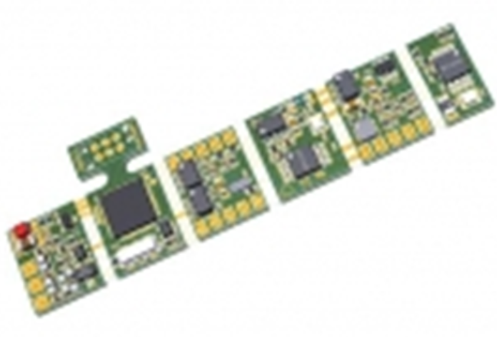
SV-Flex – Sensor Signal Amplifier Type Kalimero
For thermocouple (isolated or non-isolated), Pt100, strain gage
Measuring range up to 1000°C
Bandwidth: up to 500 Hz with 1 channel, up to 100 Hz with 16 channels
Data sheet
STEP Data
Manual

SV2a – Sensor Signal Amplifier Type 2a
(with integrated Rotor Antenna)
For strain gage, PT100, thermocouple
Sensitivity: 0.02 mV/V to 20 mV/V
Bandwidth: 0 (10) Hz to 50 kHz
Data sheet
STEP Data
Manual
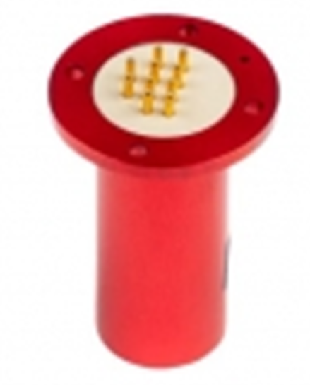
SV2b – Sensor Signal Amplifier Type 2b
(with integrated Rotor Antenna)
End of shaft, Cartridge, Turbine, Integrated Rotor Coil
For strain gage, PT100, thermocouple
Sensitivity: 0.02 mV/V to 20 mV/V
Bandwidth: 0 (10) Hz to 50 kHz
Data sheet
STEP Data
Manual
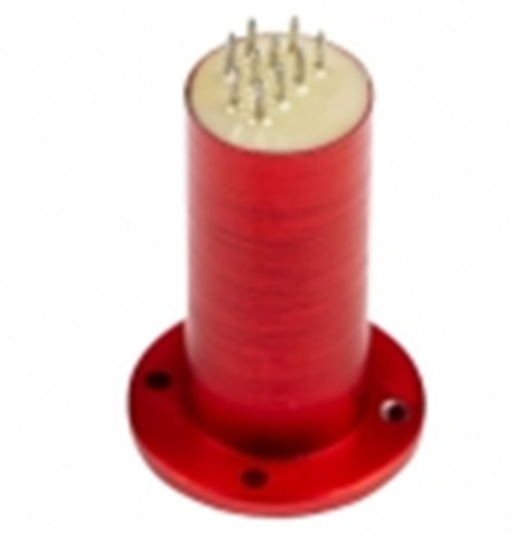
SV2bx – Sensor Signal Amplifier Type 2bx
(with integrated Rotor Antenna)
End of shaft, Cartridge, Turbine, Integrated Rotor Coil
For strain gage, PT100, thermocouple
Sensitivity: 0.02 mV/V to 20 mV/V
Bandwidth: 0 (10) Hz to 50 kHz
Data sheet
STEP Data
Manual

SV2c – Sensor Signal Amplifier Type 2c
(with integrated Rotor Antenna)
End of shaft, Miniatur Cartridge, Turbine
For strain gage, PT100, thermocouple
Sensitivity: 0.02 mV/V to 20 mV/V
Bandwidth: 0 (10) Hz to 50 kHz
Data sheet
STEP Data
Manual

SV2d – Sensor Signal Amplifier Type 2d
(with integrated Rotor Antenna)
End of shaft, Miniatur Cartridge, Turbine
For strain gage, PT100, thermocouple
Sensitivity: 0.02 mV/V to 20 mV/V
Bandwidth: 0 (10) Hz to 50 kHz
Data sheet
STEP-Datei
Manual
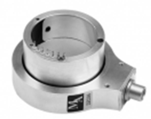
SV2La – Universal Shaft Transmitter with Sensor Signal Amplifier Type 2La
non dividable, 1 channel, with/without RMC, without rpm sensor
Beared wheel transmitter
For strain gage, PT100, thermocouple
Sensitivity: 0.02 mV/V to 20 mV/V
Bandwidth: 0 (10) Hz to 10 kHz
Data sheet
STEP Data
Manual
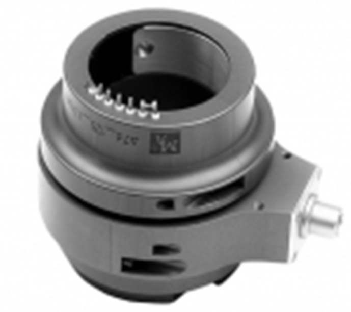
SV2Lg – Universal Shaft Transmitter with Sensor Signal Amplifier Type 2Lg
dividable, 1 channel, with/without RMC, without rpm sensor
Beared wheel transmitter
For strain gage, PT100, thermocouple
Sensitivity: 0.02 mV/V to 20 mV/V
Bandwidth: 0 (10) Hz to 10 kHz
Data sheet
STEP Data
Manual
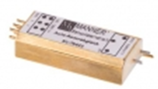
SV3a – Sensor Signal Amplifier Type 3a
For strain gage, PT100, thermocouple
Sensitivity: 0.02 mV/V to 20 mV/V
Bandwidth: 0 (10) Hz to 50 kHz
Data sheet
STEP Data
Manual
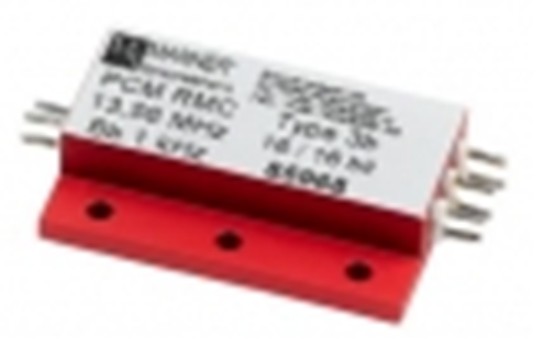
SV3b – Sensor Signal Amplifier Type 3b
For strain gage, PT100, thermocouple
Sensitivity: 0.02 mV/V to 20 mV/V
Bandwidth: 0 (10) Hz to 50 kHz
Data sheet
STEP Data
Manual

SV3c – Sensor Signal Amplifier Type 3c
For strain gage, PT100, thermocouple
Sensitivity: 0.02 mV/V to 20 mV/V
Bandwidth: 0 (10) Hz to 50 kHz
Data sheet
STEP Data
Manual

SV4a – Sensor Signal Amplifier Type 4a
For strain gage, PT100, thermocouple
Sensitivity: 0.02 mV/V to 20 mV/V
Bandwidth: 0 (10) Hz to 50 kHz
Data sheet
STEP Data
Manual
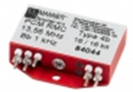
SV4b – Sensor Signal Amplifier Type 4b
For strain gage, PT100, thermocouple
Sensitivity: 0.02 mV/V to 20 mV/V
Bandwidth: 0 (10) Hz to 50 kHz
Data sheet
STEP Data
Manual

SV5a – Sensor Signal Amplifier Type 5a
For strain gage, PT100, thermocouple
Sensitivity: 0.02 mV/V to 20 mV/V
Bandwidth: 0 (10) Hz to 50 kHz
Data sheet
STEP Data
Manual

SV5b – Sensor Signal Amplifier Type 5b
For strain gage, PT100, thermocouple
Sensitivity: 0.02 mV/V to 20 mV/V
Bandwidth: 0 (10) Hz to 50 kHz
Data sheet
STEP Data
Manual
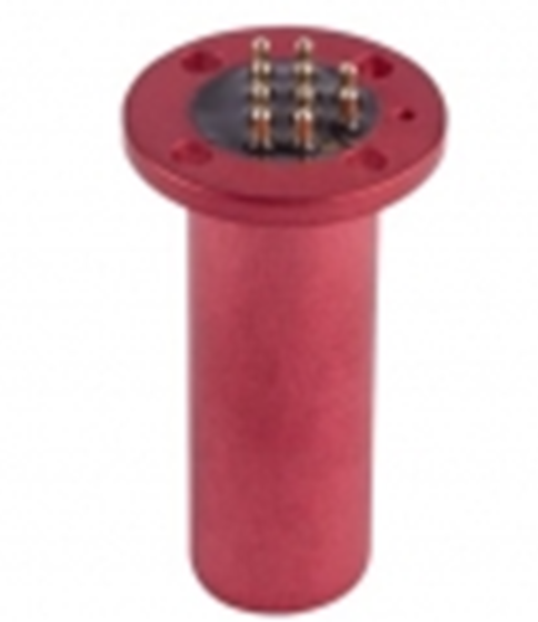
SV5c – Sensor Signal Amplifier Type 5c
Miniature Patrone
For strain gage, PT100, thermocouple
Sensitivity: 0.02 mV/V to 20 mV/V
Bandwidth: 0 (10) Hz to 50 kHz
Data sheet
STEP Data
Manual

SV5d – Sensor Signal Amplifier Type 5d
Super Miniature Patrone
For strain gage, PT100, thermocouple
Sensitivity: 0.02 mV/V to 20 mV/V
Bandwidth: 0 (10) Hz to 1 kHz
Data sheet
STEP Data
Handbuch
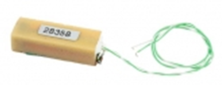
SV7a – Miniatur Sensor Signal Amplifier Type 7a
Flatchip
For strain gage, PT100, thermocouple
Sensitivity: 0.02 mV/V to 20 mV/V
Bandwidth: 0 (10) Hz to 50 kHz
Data sheet
STEP Data
Manual
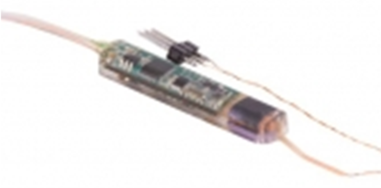
SV7b – Super Miniatur Sensor Signal Amplifier Type 7b Micro
Flatchip
For strain gage, PT100, thermocouple
Sensitivity: 0.02 mV/V to 20 mV/V
Bandwidth: 0 (10) Hz to 10 kHz
Data sheet
STEP Data
Manual
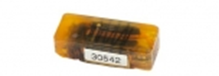
SV7ke – Miniatur Sensor Signal Amplifier Type 7ke
Flatchip with integrated Antenna (special for Chain Application)
For strain gage, PT100, thermocouple
Sensitivity: 0.02 mV/V to 20 mV/V
Bandwidth: 0 (10) Hz to 50 kHz
Data sheet
STEP Data
Manual
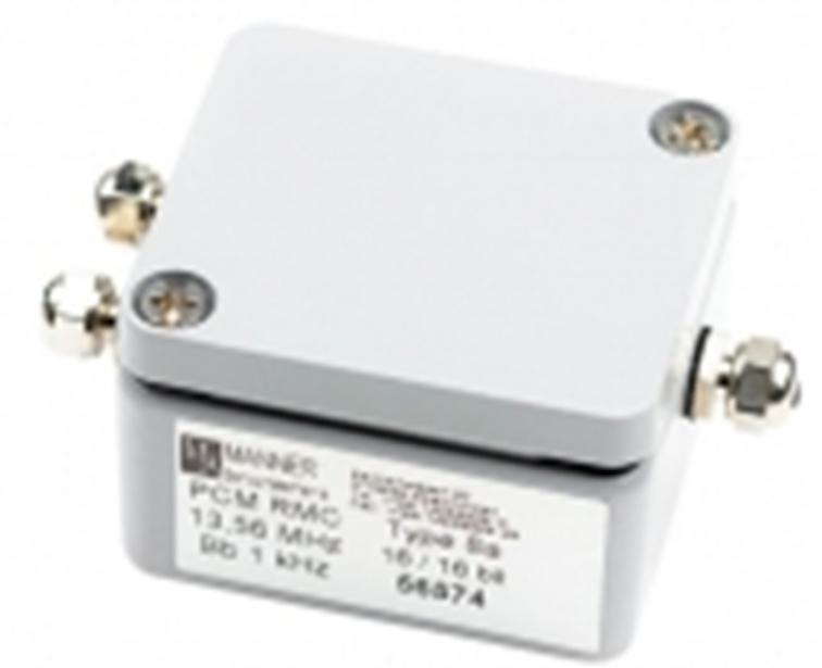
SV8a – Waterproof Sensor Signal Amplifier Type 8a
Transmitter with Antenna
For strain gage, PT100, thermocouple
Sensitivity: 0.02 mV/V to 20 mV/V
Bandwidth: 0 (10) Hz to 50 kHz
Data sheet
STEP Data
Manual

SV9 – Sensor Signal Amplifier Type 9
Transmitter with Antenna especially for Driveshaftes
For strain gage, PT100, thermocouple
Sensitivity: 0.02 mV/V to 20 mV/V
Bandwidth: 0 (10) Hz to 50 kHz
Data sheet
STEP Data
Manual
Transmission units




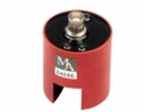
Pickup Type 2
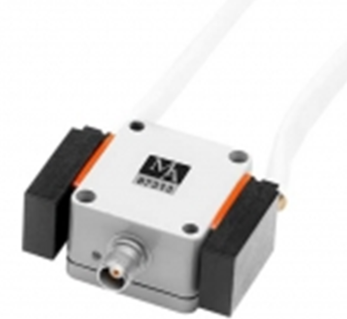
Pickup Type 3
customizable
Data sheet
STEP Data
Manual
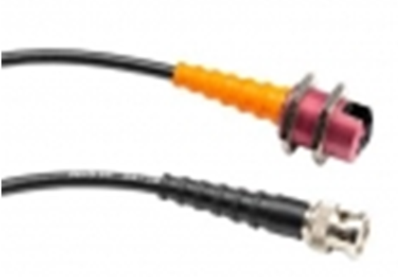
Pickup Type 4b

Pickup Type 5a

Pickup Type 5b
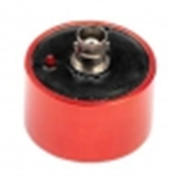
Pickup Type 5d
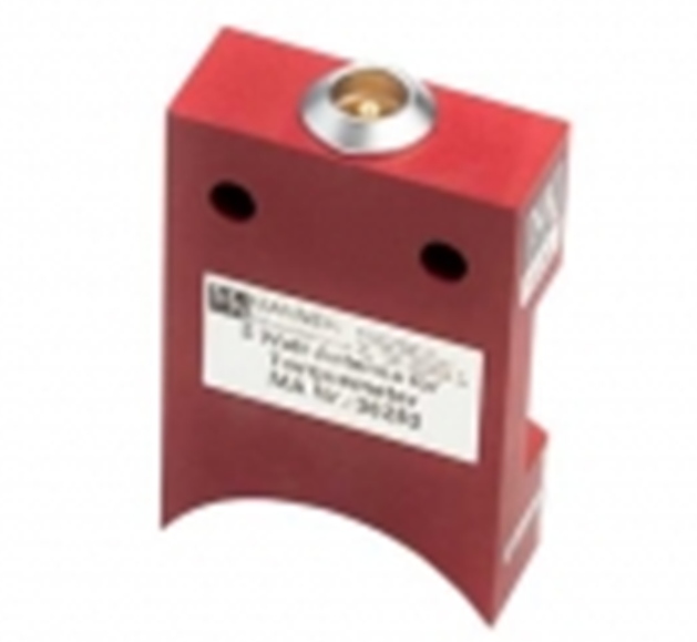
Pickup Type 5x

Pickup Type 8a
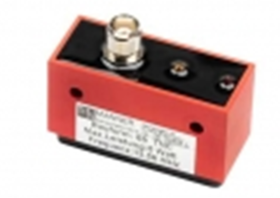
Pickup Type 8b
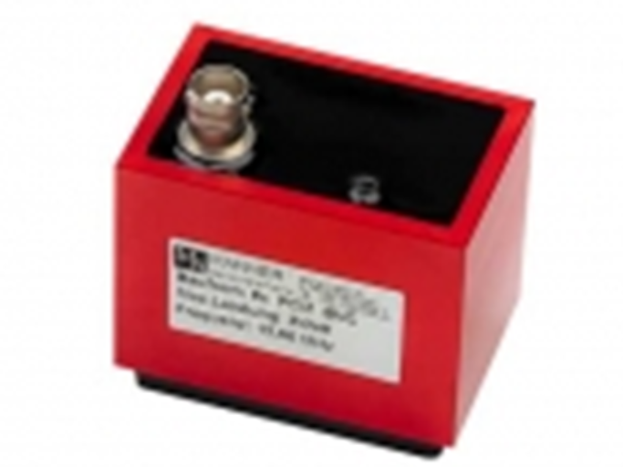
Pickup Type 8c
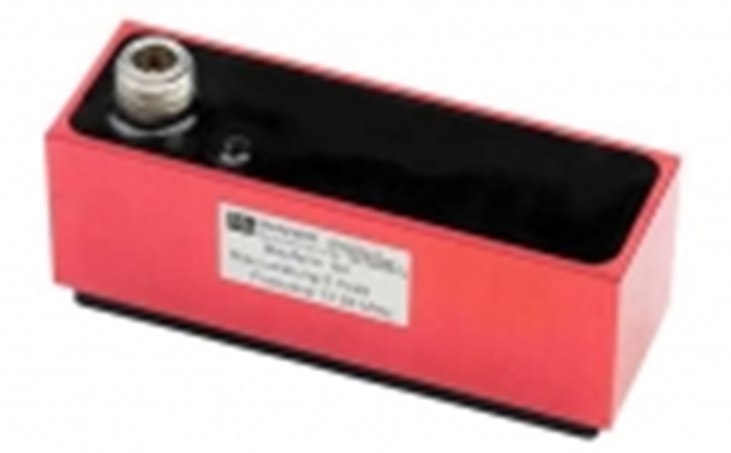
Pickup Type 8d
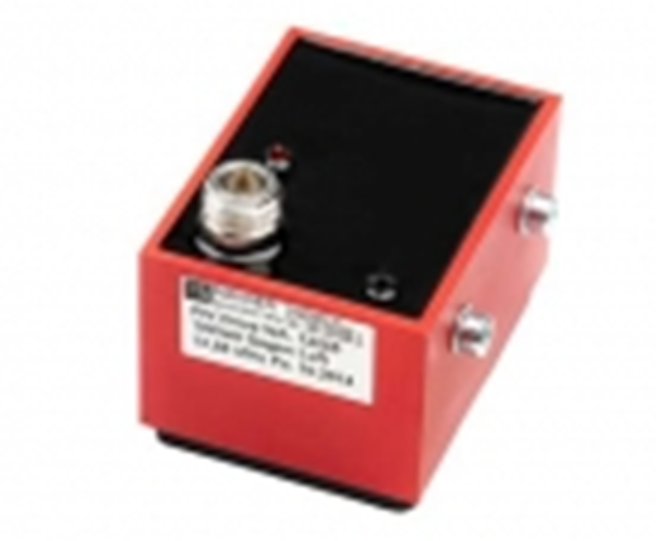
Pickup Type 8e
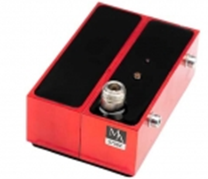
Pickup Type 8f

Pickup Type 9c
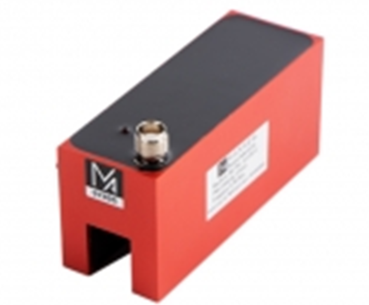
Pickup Type 9d

Pickup Type 9e
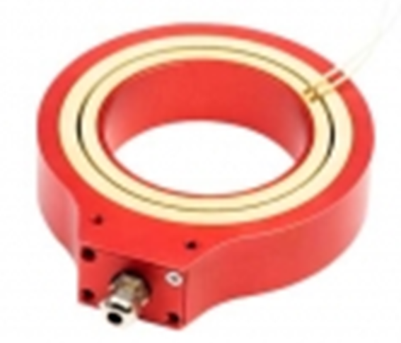
Universal Shaft Transmitter
non dividable
without Amplifier
Data sheet
STEP Data
Manual


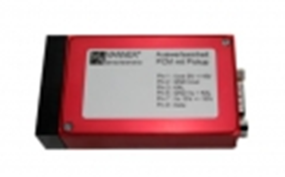
AW_D – Evaluation Unit (integrated Pick Up)
1 Channel PCM Receiver
Bandwidth: 0 t 1 kHz (10kHz)
Output: 0 to ±10 V, (0 (4) to 20 mA, frequency, binary
RF power: 1 W, 3 W
Data sheet
STEP Data
Manual
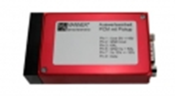
OptiMA – Evaluation Unit
außerordentlicheÜbertragungsreichweite bis zu 50mm
1 to 2 Channel PCM Receiver
Bandwidth: 0 t 1 kHz (10kHz)
Output: 0 to ±10 V, (0 (4) to 20 mA, frequency, binary
RF power: 3 W
Data sheet
STEP Data
Manual

AW_M – Evaluation Unit
1 Channel PCM Receiver
Bandwidth: 0 t 1 kHz (10kHz)
Output: 0 to ±10 V, (0 (4) to 20 mA, frequency, binary
RF power: 1 W, 3 W
Data sheet
STEP Data
Manual

AW_P – Evaluation Unit
1 Channel PCM Receiver
Bandwidth: 0 t 1 kHz (10kHz)
Output: 0 to ±10 V, (0 (4) to 20 mA, frequency, binary, USB, CAN
RF power: 1 W, 3 W, 5W
Data sheet
STEP Data
Manual
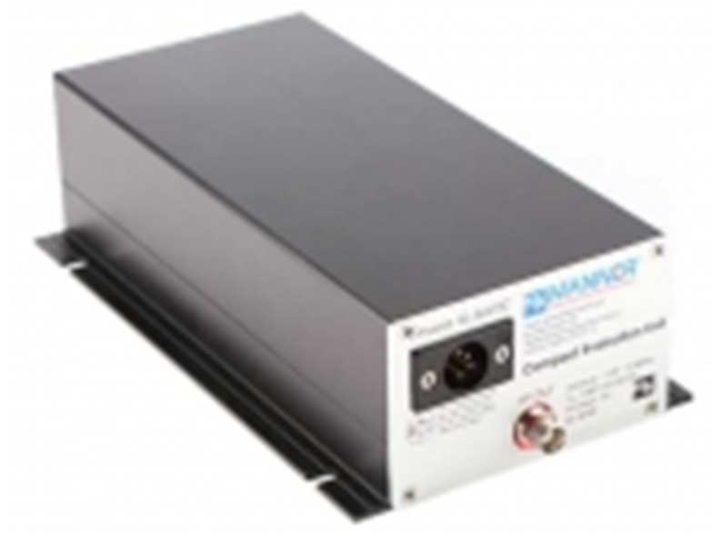
MAW_F – Evaluation Unit Digital Receiver
1 to 64 Channel PCM Receiver
Bandwidth: 0 t 1 kHz (10 kHz, 50 kHz)
Output: 0 to ±10 V, (0 (4) to 20 mA option
Digital interface (option): USB, Ethernet (TCP/IP), EtherCAT
Data sheet
STEP Data
Manual

AW42TE – Evaluation Unit (42TE)
Multi Channel PCM Receiver 42 TE
Bandwidth: 0 t 1 kHz (10 kHz, 50 kHz option)
Output: 0 to ±10 V
Interfaces (option): USB
Data sheet
STEP Data
Manual

AW84TE – Evaluation Unit (84TE, 3HE)
Multi Channel PCM Receiver 84 TE
Bandwidth: 0 t 1 kHz (10 kHz, 50 kHz option)
Output: 0 to ±10 V
Interfaces (option): USB
Data sheet
STEP Data
Manual
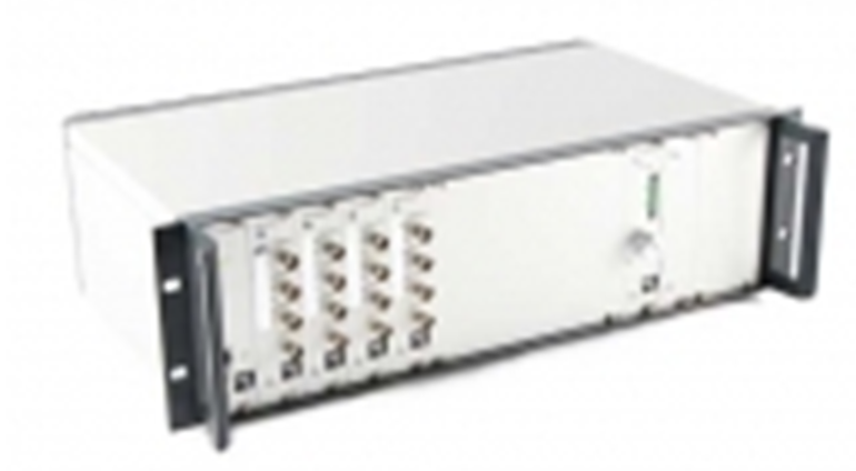
AW84TE – Evaluation Unit (84TE, 6HE)
Multi Channel PCM Receiver 84TE HE6
Bandwidth: 0 t 1 kHz (10 kHz, 50 kHz option)
Output: 0 to ±10 V
Interfaces (option): USB
Data sheet
STEP Data
Manual
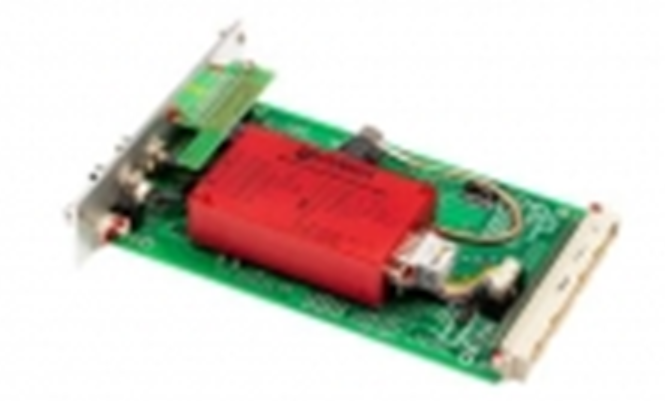
AW_ES_MGC – Evaluation MGC Plugin Unit
1 Channel MGC-Plugin Unit PCM Receiver
Bandwidth: 0 t 1 kHz
Output: 5 to 15 kHz
RF power: 3 W
Data sheet
STEP Data
Manual
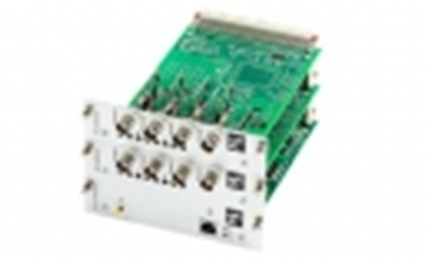
AW_ES – Evaluation Unit
Multi Channel PCM Receiver ES
Bandwidth: 0 t 1 kHz (10 kHz, 50 kHz option)
Output: 0 to ±10 V
Interfaces (option): USB
Data sheet
STEP Data
Manual
Data reception




MANNER offers its customers tailor-made software for their telemetry systems. This enables them to make the necessary settings themselves – conveniently via their PC.
